1. INTRODUCTION
1.1 BACKGROUND
1.1.1 Background - Aerosol Cans
1.1.2 Analysis of can body strength
1.1.3 Background - Ultrasonics
1.1.4 Application of high power ultrasound to metal forming.
1.1.5 Methods of generating high power ultrasonic vibrations
1.2 ULTRASONIC SYSTEM FOR FORMING AEROSOL CANS
1.2.1 Proposed mechanisms of force reduction from earlier work
1.2.2 'Most likely' mechanisms in this application
1.2.3 Ultrasonic system for forming aerosol cans
1.3 LITERATURE REVIEW
1.3.1 Application of high power ultrasound to metal forming.
1.3.2 Other industrial applications of high power ultrasonics
1.3.3 Methods of generating high power ultrasonic vibrations
1.3.4 Analysis of vibration characteristics
1.3.5 Materials for ultrasonic tools
1.4 SAFETY OF HIGH POWER ULTRASONICS
1.5 SUMMARY
1. INTRODUCTION
This project concerns the development of a new technique for forming metal aerosol cans using ultrasonic vibrations to assist the forming process. The work described forms part of a collaborative research project between CarnaudMetalbox and Loughborough University sponsored by the Science and Engineering Research Council under the specially promoted programme for the development of high speed machinery. Research at Loughborough included the development of special optical and modal analysis techniques for vibration measurement and design optimisation, while at Wantage finite element analysis was used to develop the design of new ultrasonic tools. For a general overview of project aims and achievements see Chapman and Tyrer [1].
The project involves two main areas:
1) Aerosol can manufacturing methods
2) High power ultrasonics, particularly where applied to metal forming processes.
In this chapter the reasons for the use of ultrasonics are explained and possible reasons for their beneficial effects discussed. Safety considerations when working with high power ultrasonics are also included.
A short summary of the thesis follows to indicate the content of the remaining chapters.
The background to the project includes the manufacture of aerosol cans (which was the first application of the technique), and the use of high power ultrasonics.
1.1.1 Background - Aerosol Cans
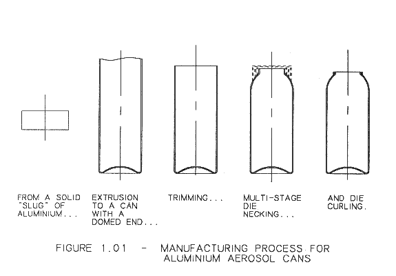
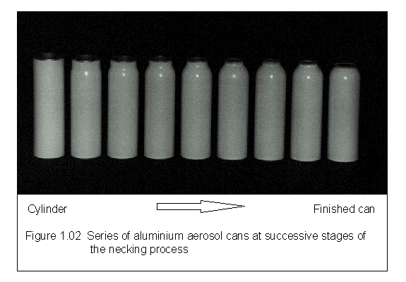
Most aerosol cans available at present are manufactured from either steel or aluminium. The production method depends on the material. Aluminium cans are produced by extrusion of a cylinder with a closed end, followed by multiple die forming operations to reduce the diameter of the open end and create the rolled end on which the valve assembly is fitted. Figure 1.01 shows diagrammatically the whole process while figure 1.02 shows a series of cans at each stage of the neck reduction.
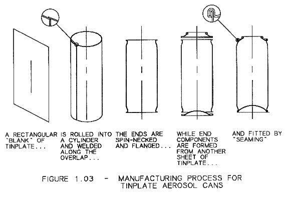
Steel (tinplate) cans are produced by a different process shown in figure 1.03. A rectangular shape is cut from sheet, rolled into a cylinder and welded along the seam. The round end pieces (pressed from another sheet of steel) are then fitted by a clinching process known as double seaming.
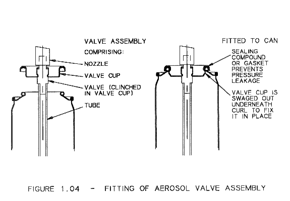
Both types of can are supplied to the filler (cosmetics / pharmaceutical companies) with the top open. Valve assemblies are supplied separately. The filler puts his product plus propellant into the can and then fits a valve assembly which is fixed by clinching (figure 1.04). To ensure that the filling operation goes smoothly and to avoid leakage after filling both the can and the valve assembly must be made to tightly controlled dimensions - typical tolerances are ± 0.1 mm.
Each can material has advantages and disadvantages. The advantages of aluminium cans are their smooth, attractive appearance and the reduced risk of corrosion (many aerosol products are corrosive). The main advantage of steel is its lower cost - the raw material cost of aluminium is relatively high and aluminium can walls must be thicker to withstand the same internal pressure (the yield strength of the aluminium used is lower than that of steel). Also steel aerosol cans may be decorated with a higher quality design because printing is done on the flat sheet - this is easier than printing onto a cylindrical can surface. To counteract the risk of corrosion of steel cans various systems are used to apply a protective coating to the inside and outside surfaces.
Most aerosol cans on sale in the UK are made from steel, primarily because of their lower cost. Aluminium cans are used mainly in small sizes for cosmetic products where the appearance advantages outweigh the extra cost.
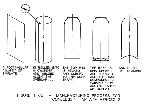
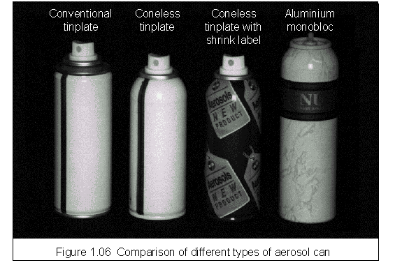
CarnaudMetalbox Aerosols UK manufactures only tinplate aerosol cans. To gain a competitive advantage, therefore, it was desirable to improve the design of the tinplate aerosol to make it more competitive with the aluminium can. This was the basis for the development of the "coneless" tinplate aerosol can, so called because the top component (the cone) has been eliminated. The rolled form on which the valve fits must be formed from the cylindrical body as in the aluminium can. This has the advantage of an attractive appearance similar to the aluminium can while maintaining the lower cost of the tinplate can (in fact the cost of a coneless tinplate can may even be less than that of the conventional can because the cost of producing the cone is eliminated). Figure 1.05 shows the manufacturing process for coneless tinplate aerosols. Figure 1.06 shows for comparison a conventional tinplate aerosol, the new coneless aerosol with and without a shrink-sleeve decoration (to disguise the unprinted weld area) and an aluminium aerosol.
The process of forming the end shape from the cylinder is much more difficult in steel than in aluminium, because the steel is harder, thinner and more liable to work hardening than the aluminium material. This means that even more forming operations are required to achieve any given reduction in diameter. A similar process has been used on steel cans by Stoffel [2] but in this case the rolled end on which the valve fits was formed by rolling the material inwards. This makes the necking operation much easier and reduces work hardening of the can material but leaves the raw edge of the material inside the can. This part of the can is particularly prone to corrosion because it lacks the protection of the layers of tin and lacquer that cover the surfaces of the can walls. This means that a steel aerosol manufactured in this way would be limited to non-corrosive products, such as solvent-based hair sprays. Water-based products such as mousses and shaving foam (for which there is a large market) could not use such a container and it is probably for this reason that commercial exploitation has not followed.
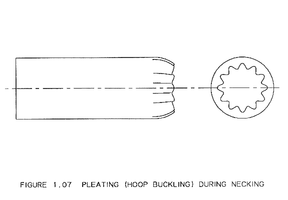
The problem is essentially that the conventional die necking process is incapable of reducing the can diameter by more than a few millimetres in each operation. If a greater reduction is attempted then the material undergoes a hoop buckling failure known as "pleating" (figure 1.07). The basis of the new necking operation is to prevent this by using a shaped plug inside the die (figure 1.08). The profile of the die and plug match, so that the gap between them is about 1.5 times the material thickness. This is sufficient to permit the material to pass through, even if it thickens slightly, but not to permit the material to pleat.
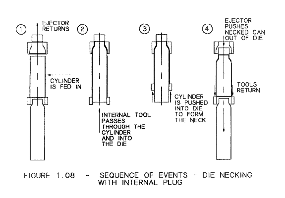
Using this type of tooling the problem of pleating is eliminated, so far greater reductions are made possible (More than 30 % reduction of diameter has been achieved in a single operation, compared to about 5 % maximum in conventional necking processes). The achievable reduction is still limited, however, by the force that can be applied. The can must be pushed into the die and the force, applied to the base, must be transmitted through the body of the can to the neck area (see figure 1.08). Thus the maximum force that can be applied is limited by the strength of the can body. If the necking force exceeds the strength of the can body then the necking will stop and the can will be crushed. Figure 1.09 shows a can crushed by excessive forming force.
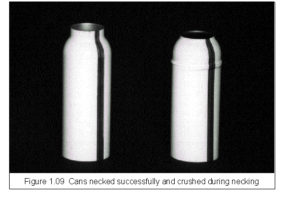
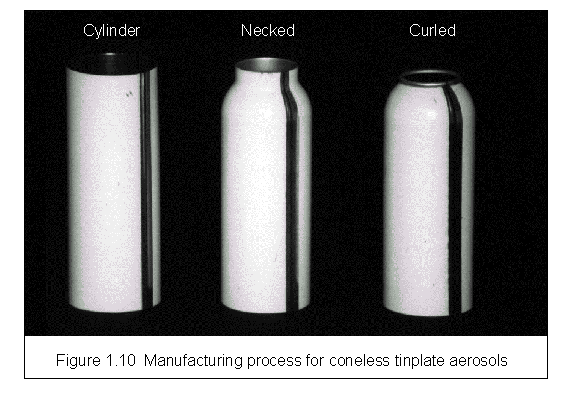
Figure 1.10 shows cans at three stages of the new process - before and after the new single die necking operation and after spin necking and curling to form the rolled end. A new spinning process to form the required "outward" curl (leaving the cut edge outside the can) has also been developed specifically for the new aerosol can, but a detailed description is outside the scope of this document.
1.1.2 Analysis of can body strength
The strength of the can body depends on a number of factors including the Young's modulus and yield stress of the material, the plate thickness and the can diameter. The mode of failure may be buckling or yield, whichever occurs at the lower level of applied force. The yield strength of the can is easily calculated:
| Fy = 2.ρ.r.t.σy | where |
Fy = yield force r = can radius t = can thickness σy = yield stress |
| i.e. Yield force is yield stress times area. | ||
The formula for buckling collapse is more complicated. Roark [3] page 689 gives the following for critical stress in a thin walled cylinder:
| where |
σ' = critical stress E = Young's Modulus ν = Poisson's ratio |
but suggests that measured values are typically between 40 and 60% of this theoretical value. Taking 40% and multiplying by the cross sectional area gives the predicted collapse load in buckling:
| where | F' = buckling force |
Into these formulae we can put the known values for the can geometry and the material properties of the steel as follows:
E = 210 GPa, σy = 240 MPa, r = 22.5 mm, t = 0.21 mm, ν = 0.3
The result is a calculated yield load of 7.1 kN, and a buckling load of 14.1 kN. This suggests that the mode of failure for this type of can will be yield. The measurements described in section 6.5 confirm this, and the measured collapse force matches this calculated value well.
The mode of failure and the formula describing the collapse load are important to determine what could be done to improve the process. Theoretical analysis of the neck forming (appendix 1) indicates that the forming force is proportional to yield stress, diameter and material thickness (and is also dependant on the amount of reduction, the work hardening characteristics of the material and friction). Since both the forming force and the strength of the can are proportional to the same three parameters, varying these parameters will not improve the forming process or permit a greater reduction. This can be achieved only by reducing friction or by reducing work hardening of the material.
In fact this is oversimplifying the situation slightly. The force required to form the neck depends on the yield stress in the hoop direction, while the can strength depends on the yield stress in the axial direction. The tinplate sheet is not isotropic - the rolling process imposes a "grain direction" that is visible to the naked eye. The nature of the anisotropy varies from one material to another but for the type of tinplate used for this product ("temper 2") the yield stress is about 5% less along the grain than across it. The 45 mm diameter aerosol cans are usually made with the grain direction along the can (called "H-grain") in order to maximise the efficiency of material usage within the sheet sizes available from tinplate suppliers. This is not ideal because the higher yield stress in the hoop direction increases the forming force while the lower axial yield stress reduces the strength of the can body. Making the cans with the grain direction around the can ("C-grain") improves the process. To manufacture 45 mm "coneless" aerosols C-grain material was specified. The small cost penalty associated with this is far outweighed by the improved neck forming.
Apart from the (marginal) issue of grain direction, there are three methods of maximising the achievable necking reduction:
1) Minimise work hardening
2) Minimise friction
3) Radically change the nature of the forming process.
It was thought that the use of ultrasonics might help to achieve some or all of these aims.
1.1.3 Background - Ultrasonics
Ultrasound can be defined as mechanical vibrations in a solid or fluid at a frequency higher than the range audible to humans. The lowest ultrasonic frequency is normally taken as 20 kHz. The top end of the frequency range is limited only by the ability to generate the signals - frequencies in the gigahertz range have been used.
Historically ultrasonic vibrations have been used for a huge variety of applications. These can mostly be divided into two broad categories: low power ultrasound (up to about ten watts) and high power ultrasound (ranging from hundreds of watts to tens of kilowatts). Low power applications include non-destructive material testing (particularly for welds), fluid level measurement, thickness measurement and medical imaging. These applications are not highly relevant to the subject of this research and so will not be discussed in detail. High power industrial applications of ultrasound include welding of metals and plastics, ultrasonic cleaning and sonochemistry (altering rates and / or products of chemical reactions). Some of these are relevant to this research because there are common problems in generating, transmitting and controlling the ultrasonic vibrations. For a general review of these and many other applications of high power ultrasonics the reader is referred to a very comprehensive review by Perkins [4]. For more detail Vigoureux [5] gives a detailed account of the physics of high-power ultrasound while Puskar [6] gives a comprehensive description of experimental work in this field, particularly in Eastern Europe where much of the research has been conducted.
A common feature of all high power applications is the use of frequencies at the lower end of the scale (i.e. in the range 20 to 60 kHz). This is because the power available is limited by mechanical stress in the vibrating parts (as described further in section 3.8). Conversely higher frequencies (and square waves or step functions that include high frequency harmonics) tend to be used in measuring applications because the shorter wavelength offers greater accuracy, and at low power mechanical stress is not a problem.
In the following sections the application of high power ultrasound to metal forming is discussed, along with methods of generating the ultrasonic vibrations and the benefits obtainable.
1.1.4 Application of high power ultrasound to metal forming.
The history of research into the use of ultrasound in metal forming is discussed in section 1.3.1. The technique has been assessed in diverse operations including wire drawing, tube drawing, deep drawing, wall ironing and necking, also called nosing or upsetting (i.e. reducing the diameter of one end of a cylinder). In general the use of ultrasound has led to some reduction in the forming force and / or increase in the maximum strain achievable. Note that a reduction in forming force is not, in itself, particularly useful, but an increase in maximum strain can have a dramatic effect because this may permit the use of fewer operations to manufacture a product or even make possible a product that otherwise could not be formed.
The application most similar to the work described in this thesis was reported by Skachko, Pashchenko et al [7], [8]. This group applied high-power ultrasonics to the forming of an aerosol neck, and found that it was possible to reduce the number of operations required from 9 to 3 using ultrasonic vibrations in the axial and / or the radial directions. It is likely that the number of operations could not be further reduced because of hoop buckling (pleating) as described in section 1.1.
This problem would have been much more severe had the can material been thinner and harder as a steel can is. In this case the use of a shaped plug is essential to prevent pleating. Note that once the problem of pleating is solved more importance is placed on the effectiveness of the ultrasonics, because this is the only factor that limits the achievable reduction. It is for this reason that the research into ultrasonic dies has been carried out at CarnaudMetalbox.
1.1.5 Methods of generating high power ultrasonic vibrations
To generate and maintain vibrations in an object a transducer is normally used to convert an electrical signal to mechanical motion. A simplified description of the two most common types of transducer (magneto-strictive and piezo-electric - see figure 1.11) will be given here. The published literature relating to ultrasonic transducers for power generation is discussed in section 1.3.3.
The first type of transducer works on the principle of magnetostriction, by which a magnetic field causes elongation of certain metals (nickel alloys are usually used). A coil of wire wrapped around a metal core creates a magnetic field proportional to the electric current and the core expands and contracts as the field changes. A biasing field is required to obtain a (relatively) linear response; this may be achieved using permanent magnets or a dc biasing current. The core is usually laminated to minimise eddy currents within it.
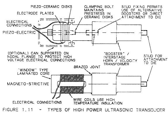
The piezo-electric transducer consists of a number (normally 2 or 4) of piezo-ceramic disks clamped between metal blocks by a high tensile screw. Under the action of an applied alternating voltage the disks expand and contract, transmitting vibrations to the blocks. The disks are liable to fracture if subjected to tensile stress so they are preloaded by the blocks and screw to ensure that a compressive stress is maintained at all times.
Magneto-strictive transducers are extremely robust (almost unbreakable) and can work over a wide frequency band, so are tolerant of frequency mismatching; their disadvantages are largely associated with inefficiencies caused by non-linearity in the magneto-strictive effect, eddy currents in the core and resistance losses in the wire coils. These limit the vibration amplitude that can be generated and can cause overheating (the coils are often wound with PTFE-insulated wire to prevent melting). Also the laminated cores are not easily fitted to a vibrating tool - often the cores are brazed to a solid part on which the tool can be fitted using a stud. The addition of this part naturally increases the losses still further. The recent development of magnetostrictive transducers based on rare earth - iron alloys may lead to solutions to these problems (Lhermet & Claeyssen [9]).
The piezo-electric effect tends to be more linear, and because it converts the electrical signal directly to mechanical movement there are no other sources of inefficiency. For this reason they operate with much higher efficiency and (given that only a certain amount of power is available) they can maintain a higher operating amplitude. Some early transducers of this type had a poor reputation for reliability, with fracture of the bolt and / or the disks as the mode of failure. This was to some extent a by-product of their high efficiency. Given a fairly low level of power input with the transducer under no load a very high vibration amplitude could be generated - causing tensile stresses high enough to destroy the transducer. The solution to this problem was in developing intelligent electrical power supplies capable of varying the power input to maintain a constant (safe) amplitude in the transducer.
Most of the work that has been carried out in the field of metal forming has used magnetostrictive transducers, largely because most of the research was carried out in the 1960's and 1970's when the piezo-electric type was not fully developed. More recently in the plastic welding industry the piezo-electric transducer has become the accepted standard. Several manufacturers of equipment for this industry have now developed highly efficient transducers that are neat, self-contained and have a high power capacity. For this research the piezo-electric transducers were chosen in order to achieve maximum amplitude under load. They have proved extremely efficient and reliable in this application. A magneto-strictive system has also been used for some research work where its lack of efficiency is not important and its relatively wide frequency range is an advantage (for vibrating the die at non-resonant frequencies).
1.2 ULTRASONIC SYSTEM FOR FORMING AEROSOL CANS
The aim of this section is to discuss the requirements of an ultrasonic system for forming steel aerosol cans. First the possible mechanisms of reduced forming force are described, and the most likely ones described in detail. This effectively fixes the type of ultrasonic die. Other requirements of the vibrating system are then discussed.
1.2.1 Proposed mechanisms of force reduction from earlier work
The reasons proposed for the observed reductions in forming force generally fall into one of three categories: changes to the material properties of the metal being formed, changes to the stress state and changes to the frictional state. A brief discussion is included here while the published work is reviewed in detail in section 1.3.1.
Some researchers, notably Langenecker [13], [14] and Izumi et al. [21] have attributed an apparent softening of the material to preferential absorption of ultrasonic energy at the grain boundaries, leading to localised heating and facilitating flow.
Another mechanism, proposed by many researchers, eg. Nevill and Brotzen [11], Pohlman and Lehfeldt [16] and Winsper and Sansome [28], [29] is that the reductions in forming force can be attributed to changes in the stress state during the vibration cycle. The argument can be applied to axial or radial excitation of the die. For axial vibration the extra stress generated by a "push" each cycle is superimposed on the average stress level. Provided the total stress exceeds the yield strength of the material then yielding will take place once per cycle, while the average stress is less than the yield strength of the material. In many metal forming applications (including this study) the force which can be applied is limited by the strength of the component. Superposition of axial stress will not help this type of process because the vibration stress generated will be applied equally to the component, causing it to yield at an average stress level lower than its actual strength. The application of radial vibrations, however, is potentially more useful. Here the vibrations may cause an increase in the hoop stress in the forming region (assisting its yielding in this direction) without a corresponding increase in the axial stress that the component must withstand. The process of stress superposition by radial squeezing is known as swaging. This was demonstrated in a laboratory experiment by McQueen and Sansome [44].
One further complication here is that when the forming force is reduced (by whatever means) the material is, by definition, less stressed, so less work hardening would be expected. Reduced work hardening would also lead to an apparent softening of the material with ultrasonics, although the effect of this would be slight.
The final proposed reason for force reduction is a change to the frictional conditions. Friction changes have been measured in laboratory tests, notably by Pohlman and Lehfeldt [16] and by Polanski et al. [17]. The friction coefficient may be reduced by separation of the surfaces, reduction of the normal force or "pumping" of lubricant over the surface. Alternatively the direction of friction may be changed - it may work at an angle to the direction of motion or, ideally, may be reversed so that friction assists the process. There is a theoretical basis for all of these possible changes:
Vibrations normal to the surface will cause a variation in the normal force. During that part of the cycle when the normal force is reduced sliding can take place with reduced friction. At the opposite part of the cycle, when the normal force is increased, the sliding may stop. Thus sliding takes place only when the normal force is reduced, so the friction force is correspondingly reduced. If the variation in the normal force is such that zero force is obtained then the surfaces separate for a part of each cycle, and sliding can take place with zero friction during this period. The reduced normal force also contributes to the lubricant pumping effect.
Vibrations parallel to the surface can cause changes in the direction of friction. If the direction is parallel to the surface but perpendicular to the direction of motion then the angle of the friction vector will be altered. The magnitude does not change (using the Coulomb friction model) so the component of friction in the direction of motion is reduced. If the vibrations are induced parallel to the direction of motion, and the vibration velocity is greater than the sliding velocity, then there will be a part of the cycle during which the direction of sliding is reversed. This must result in reversal of friction during that period. Note that these changes are heavily dependent on the relative sliding velocity - at higher forming speed the effect of the vibrations is reduced.
1.2.2 'Most likely' mechanisms in this application
From the available information it was thought that vibrations normal to the die surface (i.e. radially) would give the most beneficial effect, and this was largely confirmed by some early trials comparing the effects of axial and radial excitation. Therefore the design and optimisation work has been focused on radial-mode dies. The "most likely" force reduction mechanisms for radial vibrations are swaging (gradual deformation by successive radial squeezes) and friction reduction (figure 1.12).
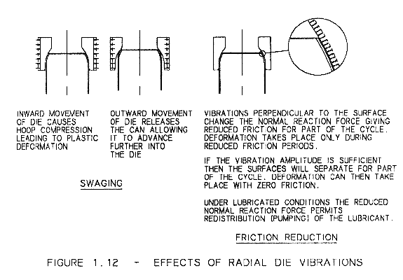
The swaging process has the potential (ideally) to reduce the forming force to zero, but this is dependent on many factors including particularly the forming speed. The faster the can is advanced into the die the more deformation will be required during each cycle, and so the higher the forming force will be.
In contrast friction reduction does not have the potential to reduce the forming force beyond a certain limit. When friction is eliminated a forming force will still be required because work must be done to deform the material of the can. The forming speed should not affect the forming force because the friction reduction depends only on the normal force, not on the sliding speed.
Thus the character of these two mechanisms is quite different, although their apparent effect on the process (a reduction in the forming force) may be similar. In fact it is very difficult to definitively state which mechanism describes the real situation, but the measurements presented in section 6.5 correspond closely to the friction reduction model in two ways. Firstly the forming force did not increase at higher speed (if anything it was found to be reduced), and secondly the forming force with ultrasonics corresponded very closely to the force calculated in an analysis that assumed zero friction (appendix 1).
1.2.3 Ultrasonic system for forming aerosol cans
It follows from the proposed mechanisms of force reduction that vibrations perpendicular to the can surface are required. This implies that the die must vibrate in a radial mode - in which it alternately expands and contracts with every point on the inside surface moving radially with the same amplitude and phase. Accordingly the aim of this work has been to develop such a die, building on past work (as discussed in the literature review) but improving the efficiency of the vibrating system to obtain maximum amplitude while minimising operating costs.
For this reason the piezoelectric type transducer was chosen, and proprietary units from two manufacturers of plastic welding equipment have been used. Only one of these transducers can normally be fitted to a die (in contrast to the magnetostrictive type) but provided that the resonance characteristics of the die are correct this is not a problem - a single transducer fitted at one point on the die can excite the required uniform radial mode. The first priority in the design of the ultrasonic system, therefore, is to ensure that the resonance characteristics are correct - this is discussed in detail in chapters 3 and 4.
The second problem for a radial-mode vibrating system is that no part of the die is stationary - there are no nodal points. A mounting system is required which permits the die to vibrate freely while providing a stationary point by which the whole system can be fixed to the machine. Again there is some prior art but a more efficient, simple and robust system has been designed specifically for this application (described in chapter 5).
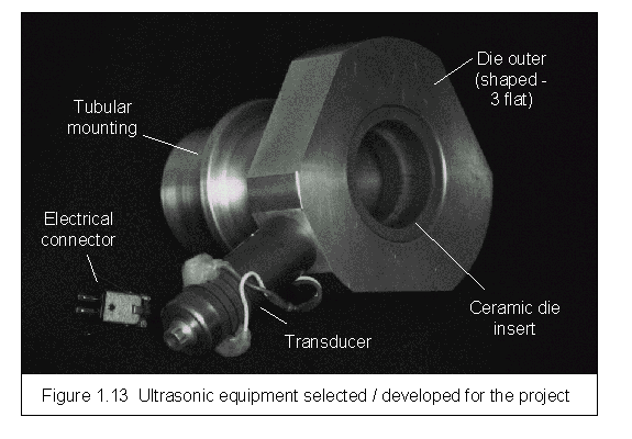
A typical system used for ultrasonic necking of metal cans in this project, comprising piezoelectric transducer, radial-mode die and tubular mounting system is shown in figure 1.13.
The purpose of this section is to identify and review previous work that may be relevant to the present study. Published papers dealing with the use of high power ultrasound in metal forming processes are listed and discussed to indicate the history of this technique. Other industrial applications, methods of analysing die vibrations and materials for ultrasonic tools are also reviewed.
1.3.1 Application of high power ultrasound to metal forming.
Much of the early research work was largely theoretical and concentrated on apparent changes to the material properties under the action of the ultrasonics. Blaha and Langenecker [10] strain tested monocrystalline metal samples immersed in tetrachloromethane irradiated with ultrasound over a wide frequency range (up to 800 kHz). The ultrasound led to increased strain to fracture and increased ultimate tensile strength. Finding that ultrasonic energy was more effective than thermal energy at reducing the tensile stress, they suggested that ultrasound might be more readily absorbed at the dislocation sites that gave rise to plastic flow.
Other work (e.g. Nevill and Brotzen 11]) suggested that a reduction in flow stress could be attributed simply to superposition, because although the mean applied stress was reduced, the peak stress was equal to the static yield stress. Another alternative, proposed by Severdenko and Klubovich [12] was that ultrasound was simply analogous to increased temperature, causing a reduction in the rate of work hardening.
Langenecker [13], [14] showed that in tensile tests the results could not be explained by acoustic stress alone. He subsequently [15] discussed the various possible mechanisms and suggested that at low energy density the superposition mechanism operated, while at high energy overheating of the sample caused softening.
Besides these "volume effects" ultrasound has also been reported to affect frictional characteristics (the "surface effect"). For example Pohlman and Lehfeldt [16] investigated not only "internal friction" effects (stress superposition) but also "external friction". Applying vibrations in three orthogonal directions to a sliding contact they found that in all cases friction was reduced. This was attributed to the vibrations shearing of the welded asperity junctions, which would permit free sliding. Later Polanski et al [17] also measured changes in friction coefficient using a wedge test and found a 40% reduction in dry friction and a 20% reduction under lubricated conditions.
Given these promising results ultrasonic vibrations were soon applied to industrial metal-forming processes, particularly forging, extrusion and drawing. Ultrasonic vibrations were used in addition to the normal equipment for the processes concerned and the aim was to improve forming conditions.
In early work on forging aluminium with ultrasound, Severdenko and Klubovich [12] reported dramatic results, including reduction of forging force to zero, virtual elimination of "barrelling" and reversal of the residual stress distribution. It was suggested that these benefits were a result of reduced friction, elasto-plastic wave formation and thermal softening effects. In similar experiments Balamuth [18] and Kristoffy [19] in the USA and Izumi et al [20], [21] in Japan observed force reductions which at low vibration amplitude could be accounted for by superposition, but at higher amplitudes the effect was greater than would be expected for superposition alone. In these experiments, however, the temperature of the test piece rose by as much as 300 °C, and the force reduction was attributed to a combination of stress superposition and thermal softening. The altered residual stresses and reduction in "barrelling" reported by Severdenko were not observed by Izumi.
In the process of extrusion of metals with applied ultrasonics Tursunov [22] measured force reductions of 20 to 40%, and noted a reduction in microhardness of the product. He attributed the effect to a reduction in yield stress caused by the ultrasonics. In the USA Jones [23] (of Aeroprojects Inc.) extruded lead and aluminium with applied ultrasonics and found that by vibrating the die (the most effective option) the force could be reduced by 15%, or the rate of extrusion (at constant force) could be increased by 88%. In this case the improvement was attributed to friction reduction. Tarpley [24] reported even greater improvements: force reduction of between 15 and 30% or rate of extrusion increased 100 to 300%.
In wire drawing ultrasonic vibrations have generally been applied to the die along the wire axis. Early investigations by Severdenko and Klubovich [25], Robinson [26] and Boyd and Maropis [27] for a wide range of materials and draw speeds showed a significant reduction (up to 65%) in the draw load and a slight reduction in the microhardness of the drawn wire. However using ultrasonics also led to severe pick-up in the die and a poor surface finish. By contrast Jones [23], while noting a similar reduction in draw force, found that the material properties of the drawn wire were unaffected and the surface finish was improved. In this case the improvements were attributed to a reduction in friction. By measuring the instantaneous stress in the wire (as opposed to the mean stress), Pohlman and Lehfeldt [16] and Winsper and Sansome [28] determined that the peak stress was unchanged. This indicated that the drop in apparent (mean) stress was due to superposition of the acoustic stress.
In a forming process limited by the strength of the product this effect would not be useful because the apparent strength of the wire would be reduced in proportion to the apparent drop in forming force. Nevertheless Winsper and Sansome [29], [30], using three dies with the centre one vibrating achieved a "genuine reduction" of up to 50 lbf in the draw force (total force figures are not given so the percentage improvement is not known). Another way to avoid this problem would be to use radial vibrations of the die and take advantage of a swaging effect due to the workpiece being compressed laterally. There are few reports of work in this area probably because of the difficulty of producing small aperture radial-mode ultrasonic dies, but a similar effect can be obtained by using a split die and vibrating one half laterally, or by installing the die in the centre of an axial mode resonator. Using this technique Oelschlagel and Weiss [31] observed force reductions from 37% to 62%. Later work by Lehfeldt [32] also included investigation of this type of die.
In the drawing of tube, where the die aperture is often larger, there was more scope for using radial vibrations. In early work, however, the axial mode was used as for wire drawing. Mainwaring [33] and Jones [23] tested axial-mode dies in plug drawing and reduced the draw force by up to 80%. Surface finish and hardness of the product were found to be unaffected. In this process (which uses a fixed plug inside the tube) it is also possible to axially vibrate the plug to obtain similar results. This is the process that Aeroprojects put into production claiming many advantages including reduced draw force, improved surface finish on the bore and the ability to achieve greater reductions and produce more complex sections. Again Aeroprojects attributed these benefits to a reduction in friction. Boyd and Kartluke [34], also derived a formula for the effects of ultrasonics based on this theory.
A notable researcher in the UK at this time (1960's and 1970's) was Prof. D. H. Sansome along with his team at Aston University, Birmingham. Some of their research into wire drawing is described above. Their research into tube drawing began by using axial vibration of the plug (as Aeroprojects) - Winsper and Sansome [35]. The beneficial effects (reduced draw load and improved surface finish) were attributed to a combination of stress superposition and friction reduction. In later work Kariyawasam, Young and Sansome [36] used radial die vibrations with a plug bar of tuned length (so that axial vibrations would be induced in the plug) to achieve a force reduction ranging from 10 to 30%.
This team also applied radial ultrasonic vibrations to deep drawing and wall ironing processes. Biddell and Sansome [37] used a variety of radial-mode dies to achieve improved depths of draw, especially at low speed, and concluded that the effect was a result of reversal of the friction vector. Later Biddell [38] reported further work again using radial dies which showed an increase of draw depth of about 12%, but this was not always achieved. The work also extended to wall ironing but it was found that for high reductions the ultrasonic system was unable to maintain the vibration amplitude. Tisza [39], [40] also reported work on ultrasonic deep drawing, in this case with a complex combined axial-radial mode die which converted axial vibrations at the transducer to radial at the die. This overcame the perceived need to use a large number of transducers arranged around the die to generate a uniform amplitude. Using a single magneto-strictive transducer an amplitude of 15 μ was achieved and the achievable deformation was increased by up to 15%. The effect was attributed to reduced "friction factor", friction vector reversal and a modified tensile strength under the action of the ultrasonics.
To avoid problems maintaining amplitude and to approach the research in a more fundamental way Sansome's team developed simpler test processes - the wedge draw test simulated deep drawing while deforming only a sector of a cylinder, while the strip ironing test simulated wall-ironing in a flat sample. Initial results for the wedge test were mixed. Smith, Young and Sansome [41], [42] reported that vibrating the punch alone produced an apparent reduction in the forming force (due to stress superposition) but no significant benefit in achievable depth of draw. However by radially vibrating the die an increase in draw depth of the order 5% was achieved. Best results were obtained by radially vibrating the blankholder [43] which gave an increase in depth of draw of the order 10%.
The wall-ironing process was simulated by drawing a strip of metal through a pair of flat dies. McQueen and Sansome [44] vibrated both dies in a perpendicular direction at approximately the same frequency (within 50 Hz). The maximum area reduction achievable was increased from 63 to 80% with ultrasonics. Note that this process simulates wall ironing with a radial-mode die and a radial-mode punch. Vibrating one die only would perhaps have been more realistic - simulating the wall-ironing process with a radial-mode die only.
The application most similar to the work described in this thesis is "tube sinking" (a term used in the tube drawing industry that is equivalent to "necking" in the can industry). In this process one end of a tube is forced into a die to reduce its diameter. Aeroprojects' work on tube drawing was also applied to tube sinking in the early stages [23]. Westinghouse also used an ultrasonic process for tube expansion [45].
More recently in eastern Europe highly relevant work was reported by Skachko, Pashchenko et al [7], [8]. This group applied high-power ultrasonics to the forming of an aerosol neck, using ultrasonic dies in the conventional process for necking aluminium aerosols, i.e. multi-stage necking with a simple parallel plug. He found that it was possible to reduce the number of operations required from 9 to 3 using ultrasonic vibrations in the axial and / or the radial directions. It is important to remember, however, that this work was applied to aluminium aerosols. Using harder, thinner material (steel) the limiting factor on reduction achievable in a conventional necking operation is buckling in the circumferential direction (pleating), and this is not significantly affected by vibrations.
In almost all applications a significant improvement in the forming process was reported when using ultrasonics, either a reduction in the forming force or an increase in the apparent formability of the workpiece. Various theories have been proposed for these observations, as further described in section 1.3.1. Despite this, widespread application in industry did not follow. Several review articles suggested that full production status was imminent [46], [47], [48], [49] and in another Biddell and Sansome suggested that industry was to blame for not applying the technology [50]. Industry would probably argue that the benefits were insufficient to justify the extra cost and complication of the ultrasonic equipment. High-power ultrasonics have been fully accepted in another section of industry (plastic welding) as described in section 1.3.2.
For a more detailed review of early work on vibratory forming (both low and high frequencies) see Dawson et al [51]. For a review of work at Aston University see Sansome [52]. Jones' review of work at Aeroprojects [23] is particularly comprehensive and includes a table of experimental results obtained from many industrial trials.
1.3.2 Other industrial applications of high power ultrasonics
Other applications of high-power ultrasonics in industry include cleaning, plastic welding, metal welding, cutting. These have largely developed in a different section of industry to the metal-forming applications, and the development of equipment to generate ultrasonic vibrations has taken a different route (this will be further discussed in section 1.3.3). Few reports of the developments in these areas have been published, possibly because most of the work has been undertaken by industry rather than academia. Nevertheless these applications will be discussed, with reference to sales literature where necessary.
Ultrasonic cleaning involves immersing the workpiece in a fluid irradiated by ultrasound, often from several sources (to obtain a relatively uniform field). The cleaning action is enhanced by agitation of the fluid, which helps it to penetrate any awkward cavities in the workpiece, and by cavitation. This is the catastrophic collapse of vapour bubbles that produce "micro-shocks" capable of dislodging dirt and even eroding the component surface - the standard test for intensity involves immersing a piece of metal foil for a set time and then counting the holes! Traditionally the fluid was agitated by multiple piezo-ceramic disks arranged around the walls of a tank (see, for example Perkins [4] but more recently the disks have been replaced by one or more tuned probes transmitting the vibrations into the fluid from above the surface. One such system is produced by Telsonic and described in OEM Design [53]. The probe systems are claimed to be more efficient because less energy is lost to the tank walls.
Another application using broadly similar equipment is sonochemistry - the use of ultrasound in liquids to affect the rate and / or products of a chemical reaction. For further details see the works of Lorimer and Mason, for example [54]. Ultrasound has also been applied to biological samples, offering improved mass transfer between cells or (at higher levels) disruption of cell walls - see Sinistra [55]. For a detailed description of the ultrasonic equipment and instrumentation necessary for this type of work (sonochemistry and biological effects) see Perkins [56].
A similar application is ultrasonic deburring [57]. Standard cleaning equipment is used with an acid slurry (chemically and mechanically aggressive) to remove unwanted material from a machined surface. The use of ultrasonics is claimed to provide better control over the rate of removal because the ultrasonic intensity can be conveniently adjusted.
Previous applications of ultrasonics for machining have been described by Neppiras [58] and Markov [59] (edited by Neppiras). The latter is particularly detailed, describing techniques for ultrasonic cutting, drilling and grinding. Typically these operations use an abrasive slurry containing hard, sharp particles, along with a relatively soft tool, into which the hard particles become embedded. The machining is accomplished by breaking microscopic particles from the workpiece.
Welding of plastics using ultrasonics has become a standard technique in many industries including packaging (e.g. joining card / plastic laminates for carton manufacture), automotive (e.g. light clusters, bumpers, fuel tanks) and many others. The process involves vibrating one component against the other while clamping them tightly together, and is described in great detail in booklets produced by the German Electrical Manufacturers Association (ZVEI) [60] and the equipment manufacturer Herfurth (edited by Rische and Abel [61]). As one component slides against the other the sliding generates frictional heat that softens both surfaces, allowing them to merge under the action of the clamping force. Typically the direction of vibrations is perpendicular to the joining faces, although this may also generate sliding motion parallel to the surface. It is important to maintain the clamping force for a short time after the ultrasonics have been turned off to allow the weld to cool and harden. The advantages of this process are efficiency (because the heating is localised at the weld area) and convenience, indeed the weld may be some distance away from the ultrasonic tool, although resonance of the components themselves may limit the weld integrity (Jagota and Dawson [62]).
Metals can also be welded using vibration energy, see Devine [63]. Ultrasonic equipment differs from that used for plastic welding in that the vibrations are applied parallel to the surfaces to be welded. The advantages claimed for this technique are its ability to weld dissimilar metals and to weld through oxide layers without the use of corrosive flux. It has been used for welding of small components, e.g. connectors to car battery leads, but is generally limited to relatively thin sections. An exception is the work described by Tsujino et al. [64] which showed that aluminium plates up to 10 mm thick could be successfully butt-welded.
More recently Tsujino et al [65] have also reported an ultrasonic sintering process that improves the density and uniformity of the material. This used three independent ultrasonic systems (a radial-mode die with axial-mode plugs at each end).
A very different application, operating currently at much lower power, is in ultrasonic motors. For example in robotics, Schoenwald et al. [66] describe an ultrasonic gripper system. This is an example of a simple rotor system - driving a contact at an oblique angle to the surface so that a small incremental movement is generated on each vibration cycle. More complex (but potentially more efficient) systems produce drive by generating an elliptical motion at the surface. This can be achieved by generating a travelling wave in one component, which may be generated by superposition of two (resonant) standing waves at a fixed phase angle. An example of this type of work is LeLetty et al. [67], who described rotary ultrasonic motors using resonant rings operating in high harmonic modes similar to the unwanted modes observed in this project. Furthermore the motor design was achieved using finite element analysis (ATILA) to include the piezo-electric effect in three dimensions. The generation of elliptical surface motion, if it could be achieved at higher power and for the more complex geometry of a metal-forming die, could offer a major improvement to the forming process. This is discussed further in section 7.2.3.
Another totally different application is sonar - the use of reflected sound waves in liquid or air to detect distant objects. Note that this is in principle quite similar to non-destructive testing, but on a much larger scale. Because of the large scale the power used in sonar detection is high, and generation techniques are broadly similar to those used for other high-power applications. The most important parameter in this case, however, is generally the coupling to the transmission medium. See, for example, Gough and Knight [68] for a discussion of the requirements of this application. This paper is notable also for the use of admittance circle plots to indicate the performance of the ultrasonic system - see section 6.2.2.
Another use of high-power ultrasonics is in material testing, where the relatively high stresses combined with the high frequency operation significantly shorten the time required to characterise the material. For example Soderberg et al. [69] investigated fretting wear while Puskar [70] and Chapman [126] among many others, studied fatigue testing under the action of ultrasonics. Note the danger this highlights - all ultrasonic tooling is prone to fatigue failure, and careful design and control of operating conditions is necessary to prevent this. This is discussed in section 3.7.
1.3.3 Methods of generating high power ultrasonic vibrations
Transducer materials to convert electrical signals to mechanical motion (or vice versa) have been developed since the 1920's. Neppiras' review [71] describes the history and characteristics of many transducer materials, including nickel / cobalt alloys (used for most high-power magnetostrictive transducers) and lead-zirconate-titanates (used for high power piezoelectric transducers). For a more recent review of the piezoelectric / electrostrictive materials see Uchino [72], who has studied actuator applications (deformable mirrors, dot-matrix printers) and ultrasonic motors.
Whymark [73] gives a detailed description of the design and evaluation of magnetostrictive transducers, including consideration of performance under load. At this time - 1956 - the optimum efficiency of this type of transducer was particularly low (42%).
Perkins [4], while reviewing all aspects of high-power ultrasonics, compares the two types of transducer. He quotes potential efficiencies of 55% for magnetostrictive and 90 to 95% for piezoelectric.
Shelley [74], reviewing the work of Sansome's team at Aston, suggested that piezo-electric transducers had been found to be too delicate for industrial applications. Rees and Rippon [75] also found piezo-electric transducers unreliable but noted in contrast the low efficiency (65%) of magneto-strictive systems. Much of the unreliability observed was probably the fault of the control systems. Wearden [76] describes a control system for tube drawing (with magneto-strictive transducers) which automatically adjusts the drive frequency to maintain resonance within 0.3%, or 60 Hz at 20 kHz. For plastic-welding systems using piezo-electric transducers a much more precise frequency control is required (for example the Telsonic system [77] maintains resonance within less than 10 Hz). Furthermore Wearden does not mention amplitude control at all, but control of the transducer amplitude is vital to the correct operation of a piezo-electric system because under no-load very little power is required to develop high amplitude (and hence high stress) in the transducer and tooling. Sonkin [78] also discusses the design of ultrasonic generators.
For further information the German Electrical Manufacturers Association (ZVEI) has produced a useful manual of the application of ultrasonics to plastic welding [60] which includes details of the transducers and control systems used. The equipment manufacturer Herfurth has also produced a booklet of similar content based on their own work [61]. This is one of several manufacturers of equipment for this industry who have now developed highly efficient transducers that are neat, self-contained and have a high power capacity. Sophisticated instrumentation and control systems have also been developed to operate them (see also [53]).
1.3.4 Analysis of vibration characteristics
The design of axial-mode ultrasonic tools is relatively straightforward provided the diameter of the tool is less than about a quarter wavelength. Selecting a length which is an integer number of half-wavelengths ensures that the tool (sonotrode) will be tuned to approximately the required frequency, and fine tuning can be achieved by further machining of the length. Young, Winsper and Sansome [79] even suggested that a tool could be attached to the end of an axial-mode resonator by simply removing an equal mass of material from the free end. This practice is not generally recommended because the joint will not be at a stress node and the fixing is likely to be destroyed by any significant vibration amplitude. The design of radial resonators is much more difficult, firstly because the relationship between dimensions and resonant frequency is more complex and secondly because the harmonic natural frequencies do not appear in a regular series (see section 3.2).
Analysis of the vibrations of rings specifically for the ultrasonic die application was carried out by Biddell and Sansome [37], [38] and by Young, Winsper & Sansome [80], [81]. These analyses are limited to specific die shapes (flat, tapered, exponential, etc.) and to the radial axisymmetric mode only. The analysis of appendix 2 is similar but anticipates analysing the die as a series of thin rings. This permits analysis of any die shape and a number of different material properties (e.g. for dies with a hard insert of a different material). Like the earlier work however this is limited to the axisymmetric radial mode of vibration, and other modes (as described in section 3.1) can be very important. Analysis of non-axisymmetric modes of rings is discussed by Den Hartog [82] and in more detail by Timoshenko [83] but this work only covers rings of thin cross-section that do not accurately model typical ultrasonic dies. Blevins [84] gives empirical formulae for natural frequencies of rings, plates and tubes, including the harmonic modes, but the first harmonic is listed as a rigid body mode. The analysis of non-axisymmetric modes of thick rings was carried out using finite elements by Gladwell and Vijay [85] and as a full (classical) analysis by Hutchinson & El-Azhari [86], [87], although their equations required matrix arithmetic with large matrices and iterative solution. Both of these analyses still involved some simplification - the shape of the ring was limited to a hollow cylinder of uniform thickness, so this work has been used only to verify the finite element results (section 2.8).
Finite element analysis has been used for assisting in the design of ultrasonic tools notably by Derks [88] who was concerned with the design of plastic welding sonotrodes. This involved finite element analysis similar to that described here but with the aim of promoting axial modes of vibration in complex cylindrical and rectangular resonators. These are resonators for which the dimension perpendicular to the vibrations is greater than a quarter wavelength, so the simple approach to sonotrode design does not work. His work would be extremely valuable in the plastic welding industry but is not directly relevant to the design of radial-mode ultrasonic dies.
The finite element method is now a well-established tool for all kinds of engineering analysis. With the ever increasing availability of computing power and the continuing development of user-friendly interfaces this trend is certain to continue.
1.3.5 Materials for ultrasonic tools
The materials that are believed to be most suitable for the ultrasonic tooling in this application are described in detail in section 3.7. Two types have been selected corresponding to the different requirements of the inner and outer components of the die. For the hard, wear resistant inner die suitable materials include tool steels, steel matrix cermets and ceramics, while for the fatigue-resistant die outer high strength alloys of aluminium and titanium have been chosen. For clarification of the die construction see figure 1.13.
For general information on tool steels see the Metals Reference Book [89] or the Properties of the En steels [90]. To obtain a hard, wear-resistant surface finish various heat treatments are possible. In particular for the nitriding steel used in this work a plasma-nitriding treatment has been used to produce a thin layer of hard material on the surface with minimal distortion of the part. The harder surface also gives a lower coefficient of friction that assists the forming process. Both the surface hardness and the friction coefficient can be further improved by the addition of a titanium nitride coating (applied on top of the plasma-nitrided surface to prevent cracking of the coating due to collapse of the substrate). These surface treatments are described by Staines [91]. The steel-based cermet used in this work is Ferro-titanit Nikro 292, manufactured by Thyssen [92] (note that this particular grade has now been discontinued by the manufacturers - the similar Nikro 128 may be used in its place). The ceramic material that has been used is sialon, a modified silicon nitride described in general by Wilson [93], specifically Syalon 101 [94].
For further information on high strength aluminium alloys (and particularly the L168 aircraft grade used in this work) see the Aluminium Reference Book [95]. The general-purpose titanium alloy Ti-6Al-4V (i.e. 6% aluminium, 4% vanadium), which has also been used, is described in detail in [96]. For a more general discussion of the engineering applications of titanium alloys (although curiously ultrasonic tools are not mentioned) see Hanson [97].
One common requirement of both components of the ultrasonic die is a low rate of acoustic loss (i.e. energy loss caused by material damping). This is particularly important for the die outer since it is generally the larger component, and the total power loss from the system will depend on the amount of each material as well as their individual damping coefficients. Unfortunately information on the damping characteristics of materials is rarely available. Even when data is available, test results must be treated with caution because the damping value obtained is dependent on the frequency and amplitude of vibration and on the nature of the test. This is described in the Metals Reference book [89] which includes a warning regarding the accuracy of the information because it is collected from various sources. A collection of results for different materials tested under the same conditions is more useful, for example Adams [98] gives good comparative data for several grades of steel, brasses, bronzes and aluminium alloys at 11.6 kHz (unfortunately titanium alloys are not included). This work suggested that the best materials for ultrasonic applications (i.e. those with the lowest damping) are aluminium alloys, followed by brasses and bronzes.
The selection of material for the die inner and outer components depends to a large extent on the requirements of the process (e.g. wear resistance and hardness of the inner according to the abraisiveness of the material to be formed), but further constraints are put on the material selection by the essential resonance characteristics of the assembly. These are discussed in detail in section 3.4. One further group of materials has been considered because of the potential to provide more flexibility in this area: aluminium matrix composites. These materials (comprising ceramic particles in an aluminium matrix) offer a significant increase in Young's modulus with minimal change in density. This increases the sound velocity in the material so that for a given resonant frequency a larger component will be required. In producing ultrasonic dies for larger diameter forming operations this change could be crucial to producing a working ultrasonic die. Furthermore the change in modulus depends on the proportion of ceramic in the composite - so by selecting the appropriate mix the material properties could be customised to suit a particular application. The damping properties of these materials have been investigated by Bhagat et al [99], [100] who found slightly higher damping in the composites than in the base aluminium alloy, but the difference was small enough at high frequency not to cause problems for ultrasonic equipment, although it was suggested that at higher strains the composite should have higher damping. At present these materials are new to the market and very expensive, but as production levels increase the cost should fall and in future these materials may become common in the ultrasonics industry.
For any combination of materials used to construct an ultrasonic die the maximum safe amplitude at which the die can operate will generally be limited by fatigue of the die outer. One very effective method of improving the fatigue resistance is shot peening. This generates a compressive stress in the surface layer to resist the growth of microcracks that are always present there. The technique is described and analysed by, for example, Fuchs [101].
1.4 SAFETY OF HIGH POWER ULTRASONICS
With the introduction of any new technology to the industrial workplace any possible health risks must be carefully considered. In the case of high power ultrasonics, as discussed in section 1.1, other industrial applications exist, and it is possible to learn from this experience. In particular, ultrasonic equipment has become almost universal in the plastic welding industry, and ultrasonic cleaning is also a commonly used process.
The health risks of high power ultrasonics fall into two categories: risks from direct contact with the vibrating parts and risks from airborne noise (including audible noise and ultrasound). Besides these there may be other risks normally associated with moving machinery (e.g. trapping points).
Normal machinery risks can be avoided by suitable guarding, as described in BS5304:1988 [102]. In the case of the aerosol forming process the forces are high enough to present some risk of amputation of a finger or even a hand. Access to the machine is also required (for setting or clearing jams) so an interlocked guard system is required.
If a user comes into direct contact with a vibrating part there a risk of disruption of the tissues and / or rapid energy transfer, causing a burn (see, for example Hill [103] for a discussion of physical effects). Despite this, it is common (though not recommended) practice in the plastic welding industry to evaluate the performance of a sonotrode (ultrasonic tool) by the "feel" of the vibrations. This practice does not normally cause injury because the fingers are only lightly touched on the vibrating parts, so energy transfer is minimal. To prevent deliberate or accidental contact with a vibrating part the ultrasonics should be electrically interlocked to the guard system.
In addition to studying physiological effects of direct contact, other researchers, e.g. Acton [104] and Wiernicki & Karoli [105] have proposed standards for safe exposure to airborne ultrasound. These indicate that while the effects of airborne ultrasound are not fully researched, there appears to be less risk from ultrasound at any given sound level than from audible noise at the same level. Applying normal legal standards for noise level / exposure time should therefore ensure that there is no risk of hearing damage. Airborne high-frequency sound is easily deflected by lightweight barriers so these standards are easily achievable.
The following is a short description of the contents of the remaining chapters.
The analysis and design of ultrasonic dies rely heavily on finite element analysis. Chapter 2 describes the theoretical basis of this, plus practical considerations using the Ansys [106] finite element program. Some methods of simplifying the analysis are discussed, along with their advantages and drawbacks. Alternative analytical approaches are also considered in chapter 2, and several are used to verify the accuracy of the finite element results.
In chapter 3 the background information on finite element analysis is applied to the design of ultrasonic dies. To describe the various natural modes of the dies a new system of nomenclature was developed. Detailed information on the process of design and manufacture is given, and the major design considerations (materials, allowable stresses, geometric constraints, etc.) are also discussed.
Chapter 4 describes a simplified system that was developed to assist the initial design of new ultrasonic dies. Design information in the form of two dimensional contour plots is given for a range of materials in appendix 5. The use of the new system is demonstrated by means of examples.
In chapter 5 the problem of attaching a vibrating die to a fixed machine is addressed. There are no stationary (nodal) points on the die so a mounting system is required which will permit the die to move with the vibrations while at the same time locating it accurately. The shortcomings of existing systems are discussed and a new mounting system is introduced.
Chapter 6 describes methods of measuring the performance of the ultrasonic system (i.e. the die and its mounting, along with the transducer required to drive it). The measurements are aimed at both characterising the vibrations in use and evaluating the effect on the forming process. The results reproduced include summary tables of information for a number of different ultrasonic dies and graphs of the force variation during the forming stroke. The accuracy of the finite element results is also indicated by comparison with the measured data.
In chapter 7 suggestions are made for areas of further work in this field. In particular, industrial pressures have required that producing an effective ultrasonic system has taken priority over understanding the reasons for its effectiveness. Alternative methods are discussed for studying the interaction between the vibrations and the forming process.
Finally chapter 8 lists conclusions drawn from the work described here, along with a discussion of their implications.
